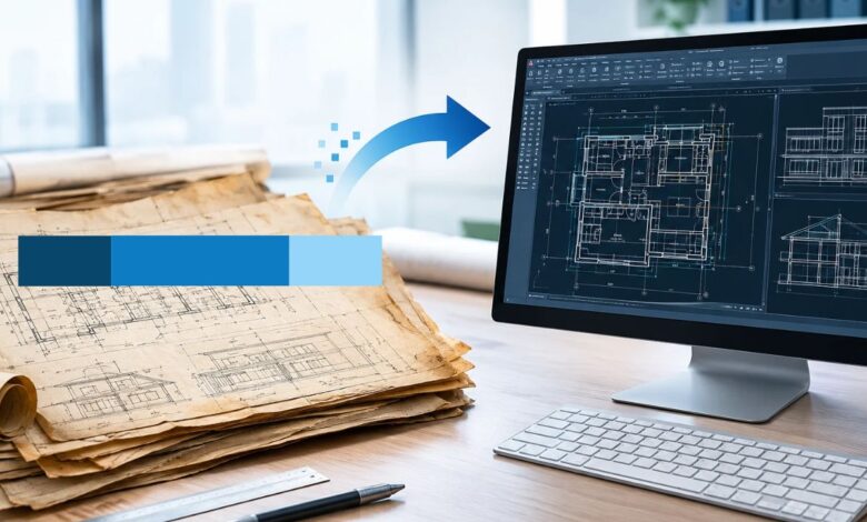
Managing historical building plans remains a primary operational challenge for US architecture, engineering, and construction (AEC) firms. Decades of project history sit locked away in physical archives, paper blueprints, mylars, or static formats like PDF and TIFF. When you take on renovation, adaptive reuse, historic preservation, or facility management projects, you must convert these static raster files into editable vector DWG files. Converting legacy drawings successfully requires a structured technical approach that balances geometric precision, proper layering standards, and drafting discipline.
Design professionals preserved plans on physical paper sheets and vellum for decades. However, relying on physical sheets or low-resolution scans in a modern digital workflow creates substantial friction. Scanned architectural drawings lack vector intelligence. Lines exist merely as pixel arrays, so you cannot query dimensions directly or isolate building components by trade. Digitizing architectural drawings transforms static paper archives into dynamic, multi-layer CAD files that integrate cleanly into modern CAD software and Building Information Modeling (BIM) platforms.
Understanding the Limits of Automated Raster-to-Vector Software
When teams need to convert scanned drawings to CAD, they often look toward automated vectorization tools or quick plugins. Optical character recognition (OCR) and automated raster-to-vector (R2V) algorithms have improved over time. However, they rarely produce the production-ready, high-precision DWG files that complex architectural projects require.
Automated conversion tools evaluate raw pixel contrast rather than understanding architectural logic or building construction systems. As a result, software might interpret a faded dimension line on an old paper blueprint as a series of disconnected splines. Similarly, it might turn a hatched brick wall into thousands of unorganized, overlapping line segments. Furthermore, automated conversion software cannot account for paper shrinkage, scanner skew, or inaccuracies present in hand-drawn originals.
Achieving true dimensional accuracy requires dedicated paper-to-CAD conversion. Experienced CAD technicians manually recreate geometry using precise numerical inputs and structural reference grids. Instead of tracing pixels blindly, expert drafters interpret historical drafting conventions. They cross-verify conflicting dimensions using geometric relationships and reconstruct the building model inside native CAD environments.
Essential Best Practices for Converting Existing Drawings to CAD
To ensure you convert existing drawings into clean, standardized deliverables, establish clear quality control protocols before drafting begins.
High-Resolution Digitization and Document Calibration
The accuracy of the final DWG drawing depends heavily on initial scan quality. Capture physical documents at 300 to 600 DPI using commercial flatbed or wide-format roller scanners configured to prevent stretching or skewing. Before drafting begins, calibrate the raster image within the CAD software environment against known reference dimensions, such as major structural column grids or overall exterior wall dimensions. This step corrects paper shrinkage and non-uniform scaling across axes.
Geometric Reconstruction and Orthographic Alignment
In professional architectural CAD conversion workflows, drafters align walls, columns, doors, and windows strictly to orthographic coordinates. Instead of tracing skewed lines from a warped blueprint image, CAD technicians establish true horizontal and vertical axes. They apply precise numerical dimensions that match the original structural callouts and design notes.
Layer Standardization and CAD File Architecture
A raw DWG file with all geometric elements placed on a single default layer creates massive inefficiencies for project teams later. Clean CAD file organization requires establishing structured layer hierarchies based on recognized standards, such as the American Institute of Architects (AIA) CAD Layer Guidelines. Separating exterior walls, interior partitions, doors, windows, millwork, dimensions, and annotations onto distinct, color-coded layers ensures long-term usability and seamless CAD-to-BIM interoperability. Professional drafting providers, such as McLine Studios, emphasize strict adherence to standard layer naming conventions and organized block libraries to ensure consistency across large multi-sheet project sets.
Integrating As-Built Conversions into Renovation Workflows
Commercial renovation, tenant fit-out, and historic restoration projects frequently present discrepancies between original design blueprints and current site conditions. Over decades of building operation, unrecorded structural modifications, wall relocations, and MEP systems updates often occur, making historic architectural drawings partially obsolete.
In these scenarios, executing an accurate as-built drawing conversion requires blending historical paper plans with updated field verification, laser scanner data, or point cloud measurements. By cross-referencing scanned historical drawings with physical site verification, drafters produce precise as-built DWG files that reflect real-world conditions rather than original, unverified design intent.
Engaging specialized architectural CAD drafting services for complex conversion projects allows AEC firms to scale drafting capacity on demand. This approach prevents firms from diverting internal senior design teams away from core design development. External technical experts bring standardized quality control procedures, fast project turnaround times, and deep familiarity with US architectural standards.
Future-Proofing Architectural Archives with CAD Accuracy
Converting physical drawing archives into accurate DWG vector files provides a foundational investment for modernizing architectural operations. Transitioning from static paper blueprints to structured vector files streamlines interdisciplinary collaboration among architects, structural engineers, MEP consultants, and general contractors. This shift significantly reduces field errors and project rework during construction.
By prioritizing manual vectorization over automated tracing software, maintaining strict CAD layering standards, and verifying spatial accuracy against real-world field conditions, AEC professionals ensure that legacy architectural drawings serve as accurate, reliable digital assets for future expansion and renovation projects.